FAQ/SAFETY NOTES
Technical Support
FAQ
-
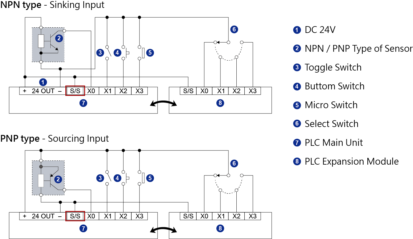
Q How to install NPN/PNP transducer on PLC?A1.General PLC (Programmable Logic Computer) could select input type NPN or PNP, by connects S/S to 24V or 0V respectively.
■ NPN input:S/S connects to 24V.
■ PNP input:S/S connects to 0V.
2.Considering PLC power supply ability, please apply external power to sensors rather than internal power of PLC.
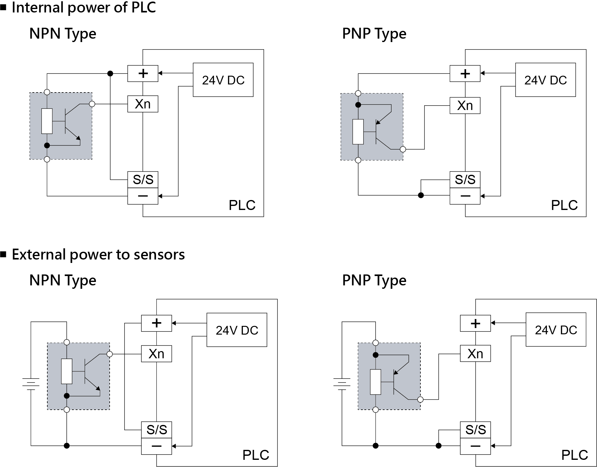
Attention:Please notice that GND of external power shall be connected to GND of PLC. -
Q MODBUS wiring?A
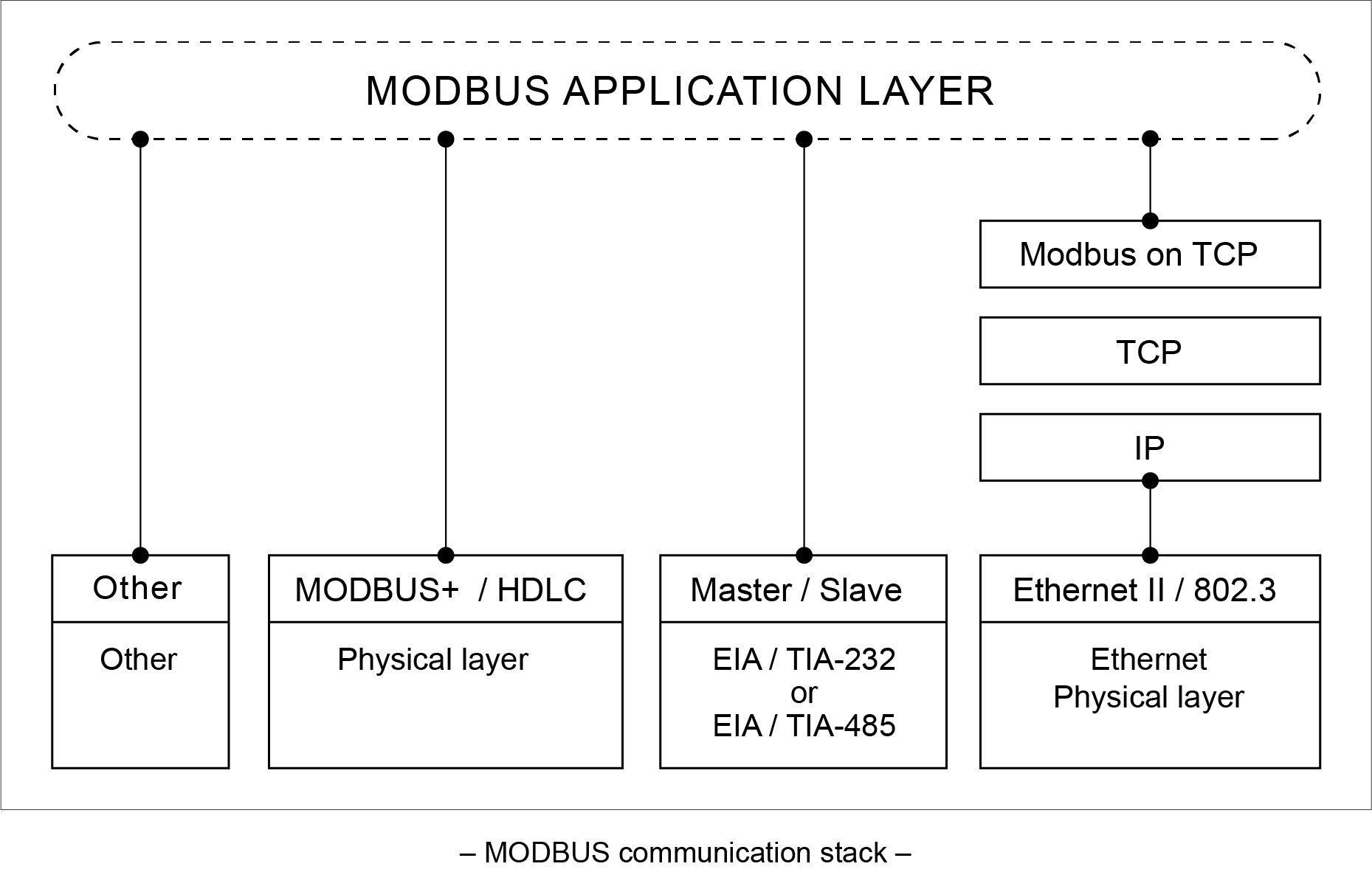
Modbus is one kind of protocols that machine can transfer data through this method. Generally speaking, MODBUS is to machines what language is to human beings.
Communication protocol is software level protocol, and different devices exchange data through the same protocol.
Then machine needs physical port to transfer data, such as EIA 485(RS485)、EIA422(RS422)、EIA232(RS232) or RJ45 Ethernet.
Attention:Device with RS485 port does not mean it must support Modbus Protocol. Please contact Device provider for more information.
1.RS485 sign:
RS485 2 wiresReceive D–
RS485 –RX–
TX–RDA
SDARDA–
SDA–A Transmit D+
RS485+RX+
TX+RDB
SDBRDB+
SDB+B
2.Connection diagram:

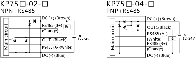
3.Examples:KP75口-02/04 Circuit wiring diagrams
MODBUS wiring method: Wire B+ connects with D+(RS485+) of your own equipment. Wire A- connects with D-(RS485-) of your own equipment.
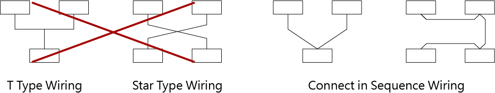
4.Make sure the principle of connection is correctly when do wiring, and do not use T type wiring method, star type wiring method or any other wiring method for convenience.
5.Keep away from high noise source when wiring. Do not use the same groove as the power wire uses in the distribution box. Externally, keep as far away as possible from devices which have electromagnetic radiation.
The transfer wire need to use shielded twisted pair wire. Normal twisted pair wire can be used when conducting short distance communication in low noise environment to reduce cost. But in high noise environment, long distance communication or in case of high communication quality is required, the dedicated transfer wire for RS-485 is recommended. It may make higher budget, but the communication quality will be improved magnificently.

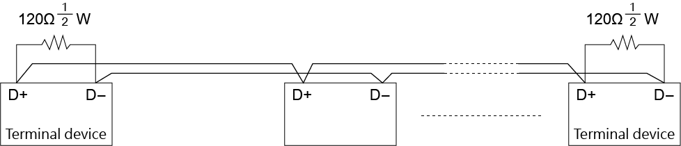
6.Terminal resistances must be parallel connected to the two terminal points of the whole communication circuit. For the twisted pair wire used by RS-485 interface, the terminal resistances should choose 120Ω 1/2 W ones.
-
Q Final check before transmitting dataA
- Check whether the communication software is working properly, including whether the communication parameters (such as ID, baud rate, check bit, delay, time-out setting) are correctly.
- Reduce environmental interferences.
- Re-wire the transfer wire, and avoid noise source.
- ID:ID can only be identical.
- Baud、Parity Check Bit:Ever part of system setting should be same.
- Delay Time:Short delay time interval may cause data lose.
- Time out:1000~500ms are recommended, depending on devices.
If everything on the system is done correctly and communications still do not work, please contact PLC provider for more PLC communication setting details.
-
Q LED on magnetic sensor does not workA
Check power supply type (AC or DC) of product
■ AC-powered product
Sensor works:LED is out of order. Please send back for examination.
Sensor doesn't work:Please refer《The Malfunction of Magnetic Sensor》
■ DC-powered product
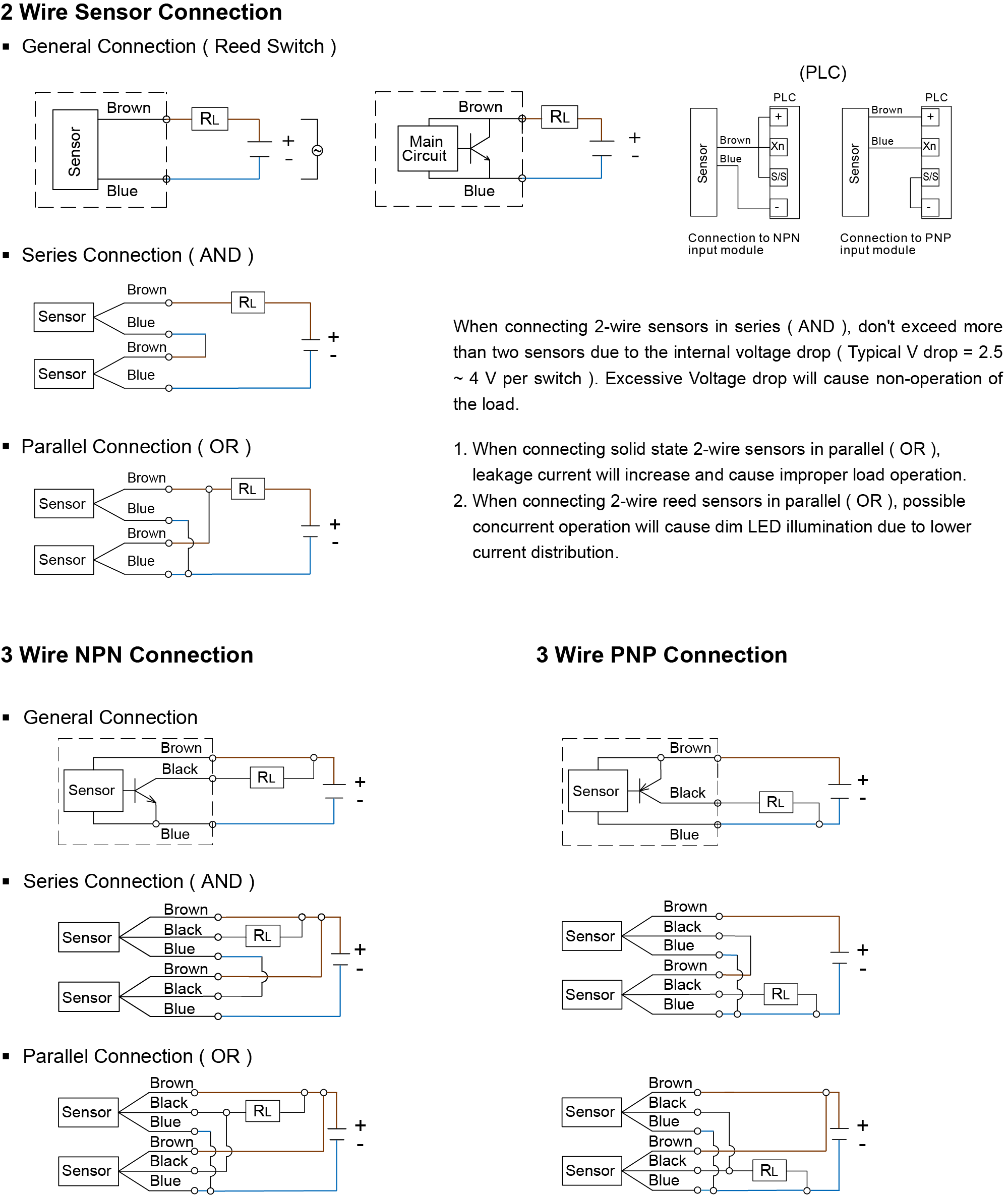
Sensor works:Check the polarity of wiring.
— Wrong:Please correct it. 《Please refer to the figure below》
— Correct:Please send back for examination.
Sensor doesn't work:Please refer《The Malfunction of Magnetic Sensor》
-
Q The malfunction of magnetic sensorA
Check wiring
■ Correct:Remove magnetic sensor from cylinder, and use a magnet to test the sensor.- Sensor works:the magnetic field of the magnet inside the cylinder is not enough or the sensitivity of magnetic sensor is too weak. Please contact our RD department.
- Sensor doesn't work:Please send back for examination.
■ Wrong:Please correct it.
-
Q Contact point is unbreakableA
Check whether the magnetic sensor is overloaded.
■ No:Check the wire distance between the magnetic sensor and the load is more than 5M or not.- Over 5M:Add an inductor ( About 1000uH ) to eliminate to capacitor impulse caused by long wiring.
- Below 5M:Please send back for examination.
■ Yes:- Exchange magnetic sensor with larger rated operating voltage, current, and contact rating.
- Use relay or PLC to drive the load indirectly.
-
Q The LED flashes and turns offA
Check whether the loading current is too high.
■ Yes:- Exchange magnetic sensor with larger rated operating voltage, current, and contact rating. 《Please refer to the figure below》
- Use relay or PLC to drive the load indirectly.
-
Q Magnetic sensor operates twice continuouslyAThe magnetic field of magnet is too strong or the sensitivity of magnetic sensor is too high.
Please contact to our RD department.
 Flow Sensor
 Pressure Sensor
 Magnetic Switch & Sensor
 IIOT Sensor
 Circular Connector
 Silencer